SVM is a sophisticated digital control algorithm employed in modern Inverters for the generation of a three phase pure sine AC voltage. SVM Inverters are mostly used to power high performance industrial drives such as three phase AC induction motors. Unlike the conventional sinusoidal PWM, this form of modulation utilizes more available DC supply voltage (15% more voltage output), produces a sine wave with less Total Harmonic Distortion (THD) and offers more degree of freedom in the implementation [1].
Lots of papers have been published on this topic, but many are too complicated for comprehension by many average learners, while others have failed to provide in-depth implementation details. This piece provides all the necessary information required to design and implement practical SVM Inverter in a simplified format.
The basic theory of Space Vector Modulation
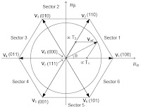
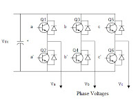
The principle of space vector modulation is based on the application of space vectors as shown in the space vector hexagon of figure 1.1. The diagram of basic three phase inverter is shown in figure 1.0. As the IGBTs/MOSFETs in fig 1.0 are switched on and off, eight possible switching vectors V0 through V7 are realised. These switching vectors consists of six active switching vectors (V1 to V6 ) and two zero (non-active) vectors (V0 and V7) as shown in figure 1.1.
Referring to figure 1.1, the Vref is the resultant output voltage from the SVM Inveter. Implementing space vector modulation requires the reference voltage Vref to be generated, and this is achieved by sampling two adjacent vectors of the Space Vector hexagon within a given time period Ts = 1/ Fs.


Figure 1.0 (left): 3 phase inverter; and fig 1.1 (right): Space Vector Hexagon
SVM Design
Space Vector PWM control is realized using the following steps:
Step 1: Determine |Vref| and angle (α)
Step 2: Determine switching timing T1, T2, T0
Step 3: Determine the switching sequence
Figure 1.4 shows the Pictorial analysis of the reference voltage Vref.
Step 1: Determination of Vref, and angle (α)
The magnitude of the voltage reference Vref is expressed as,|Vref| =m * Vdc
Where, m is the modulation index.
The modulation index m of SVM Inverter normally ranges from 0 to 0.866.
NB: Magnitude of Vref is directly proportional to modulation index.
From fig.1.4, the angle α is given as,
If Vref is built up at time t = 2.5ms for 50 Hz fundamental frequency [2], then the angle α is calculated below with Pi = 180 degrees:
Step 2: Determination of time duration T1, T2, T0
The sampling time Ts is expressed as:Several formulas exist in theory for calculating the precise value of T1 and T2 [3] [4]. For this implementation, the Values of T1 and T2 were computed using equation 1 and 2:
Step 3: Determine the switching sequence
Possible Solutions
Various strategies for selecting the order of vectors, and which zero vectors to use exist. The Strategy adopted will affect the harmonic content and the switching losses. This implementation relies on Symmetric Sequence SVM algorithm due to the low THD associated with it [5].Symmetric SVM Algorithm
The timing sequence and the resulting switching waveform for Symmetric Sequence SVM in sector 1 is shown in figure 1.2.Figure 1.2: Typical witching waveform of symmetric SVM in Sector 1
For the Symmetric SVM sequence, the expected waveform of the switching signals for the upper arm transistors in each of the six sectors of the hexagon are shown in figure 1.3.
Figure 1.3: SVM waveforms for the six sectors
Table 1.0 shows the sequence of vectors for the six sectors.
Design specifications
Calculations
The switching times for T0, T1, and T2 were computed as follows:
T1 = 200us × 2/√3 × 0.6 × sin (60-45) = 36us
T2 = 200us × 2/√3 × 0.6 × sin 45 = 98us
Therefore, T0/7 = Ts − (T1 + T2) = 200us − (36 + 98)us
T0/7 = 200us − 134 = 66us
Therefore, T0 = T7 = 66us/2 = 33us
Hence,
T0 = 33us
T1 = 36us
T2 = 98us
The implementation involved writing the required code that will actualize the Space Vector Modulation. The flow chart of figure 1.5 was used to develop the SVM code.
Figure 1.5: Design flowchart
Table 1.2 shows the hex equivalence of the SVM data required for firmware implementation. The two lower bits (bit 0 and 1) of the data line are filled with zeros. The code that implements the SVM algorithm can be accessed here - SVM Code.
Table 1.2: The hex equivalent of the switching vectors
Vectors
|
A,B,C,A’,B’,C’
|
HEX
|
V0
|
000111
|
1Ch
|
V1
|
100011
|
8Ch
|
V2
|
110001
|
C4h
|
V3
|
010101
|
54h
|
V4
|
011100
|
70h
|
V5
|
001110
|
38h
|
V6
|
101010
|
A8h
|
V7
|
111000
|
E0h
|
The complete schematic for this implementation is shown in figure 1.6. For more description of the schematics, please see the video demo below.
Figure 1.6: SVM Inverter schematic
DEMO Video: SVM INverter
Simulation Results and Discussions
The resultant SVM waveforms generated from the microcontroller are shown in figure 1.6. The result is in agreement with the theoretical symmetric SVM patterns shown in figure 1.3.
Figure 1.6: SVM signals from MCU
The phase voltages (Va, Vb and Vc) generated from the SVM inverter are shown in figure 1.7. It can be seen that the phase voltages are pure sine wave. Figure 1.8 shows the phase voltages with a phase difference of 120 degrees.
Figure 1.7: The phase voltages from the SVM Inverter
Figure 1.8: result showing the phase difference of 120 degrees
Conclusion
The aim of this work which was to generate a pure sine wave from a DC using Space Vector Modulation was successfully achieved, as demonstrated in the results.
Why not give it a trial, and see how Space Vector Modulation helps you realize a pure sine wave Inverter!


What's the code for the microcontroller , please?
ReplyDeleteFollow this link for the code: http://electrotech4u.blogspot.co.uk/2013/12/code-for-space-vector-modulation.html
Deletehi my friend plz i need your help can you contact me at this email seul0au0monde@yahoo.fr
DeleteHi, it's possible to have the C code for SVM built with MPLAB or other compiler? TKS
DeleteHi my name is Debbie Zepeda, a graduate student at Mississippi State University in the Electrical and Computer Engineering Department. I am also a graduate research assistant that is involved with a 3 year competition with 15 leading universities across North America that concludes in June. GM donated a conventional vehicle to all 15 universities, where respective students take apart and reassemble as an electric vehicle.
ReplyDeleteEcoCAR3 is our next competition starting fall 2014 and my part in this competition is to help students at their respective universities understand what electric motors and transmissions do on a powertrain for those who are inexperienced with automotive engineering. To assist these students, I am developing educational modules that will be posted to nterlearning.org. This is a request for permission to use photos (figure 1.0, 1.1, 1.2, and 1.3) on this blog.
Please contact me at your earliest convenience regarding these pictures. Thanks and I hope to hear from you soon.
You are free to use any information on my blog so far u provide appropriate references to avoid the issue of plagiarism.
Deletehello, very good job.
ReplyDeleteI wonder if the program has the option to vary the frequency.
thx
There is no such option. The fundamental frequency depends on the output filter design: Fc= square root(fundamental freq X switching freq)!
DeleteSir its great explanation i ever gone through,sir if possible will you provide a link for code using "C". I am using dspic33ep256.
ReplyDeletehello , i wanna get waveforms by "simulink" ,how ?
ReplyDeletethx
This comment has been removed by the author.
ReplyDeleteThis comment has been removed by the author.
ReplyDeleteHello,
ReplyDeleteIt might be very basic question but suppose we assume any reference voltage 'Vref' in hexagonal space.To generate 'Vref' respected to 3 phase volt. Do we have to rotate it through all 6 sectors? if , in that what will the angle steps that we have to follow.
Thank you in advance.
Hello would you be so kind to send me the simulation file
ReplyDeleteA karolinamarialopézjhonson@hotmail.com
Thank you very much
Hello, you would be so kind to send me the simulation file
ReplyDeleteA karolinamarialopezjhonson@hotmail.com
Thank you
Can someone send the simulation file please to aamir.1919@outlook.com?? its very urgent
ReplyDeleteCan you please tell me what should be the value of L & C to get a 50Hz output sinusoidal wave?
ReplyDeletecan you send me simulation at benkaddourhouari@gmail.com
ReplyDeleteFor those requesting simulation file - u need isis software to draw cct and simulate using code.if u need me to do work again for u then contact me on uchelectrotech@gmail.com
ReplyDeleteTHANK YOU VERY MUCH SIR
ReplyDeletethank you sir and is there any m file for svpwm with bldc motor
ReplyDeleteExcellently explain SVPWM by you thank you very much.
ReplyDeleteI am trying to make some changes in code for variable output frequency and voltages.For gaining proper V/Hz ratio for induction motor.
Again thank you very much.
Hi sur, can you send me the .HEX file to jad.bara@gmail.com
ReplyDeleteThank you very much
Hello sir,
ReplyDeleteThe explanation was awesome & im hvng a doubt in the program what u've posted. Im trying to rewrite the code in embedded C for 8051 microcontroller. Ive finished writing the codes for delay generation. But for Sector selection, I've to calculate the initial alpha and according to the alpha, sector will be determined and then, the respective port gives PWM signal. So in the code given, can you please tell me where is the alpha calculation? THanku
can you send code to implement it
ReplyDeleteGreat and I have a super proposal: Who To Contact For House Renovation house renovation book
ReplyDelete