
Information Dissemination!
Information dissemination has become very indispensable in many areas of modern life.
Dot matrix digital display system is a flexible information display system used for high impact visual communication that satisfies the needs of different applications. This post features the design and implementation of a basic Dot matrix information display system.
Dot-matrix system consists of LED dots arranged in a matrix pattern to display different characters and symbols. See figure 1 for a visual familiarisation of a dot matrix display system. Dot-matrix system adopts the principle of persistence of vision to display catchy information using different styles and effects.

The design goal for this dot matrix system is to display a set of symbols scrolling from right to left repeatedly once the system is powered. The system design block diagram is shown below in figure 2.

Dot matrix digital display system is a flexible information display system used for high impact visual communication that satisfies the needs of different applications. This post features the design and implementation of a basic Dot matrix information display system.
More light on Dot-matrix display
Figure 1: Dot matrix display board
The system design
The design goal for this dot matrix system is to display a set of symbols scrolling from right to left repeatedly once the system is powered. The system design block diagram is shown below in figure 2.
Figure 2: Dot matrix block diagram
The schematic of the dot matrix system is shown below in figure 3. The key components of the dot matrix system are PIC16F84A and 4017 shown on the schematic.
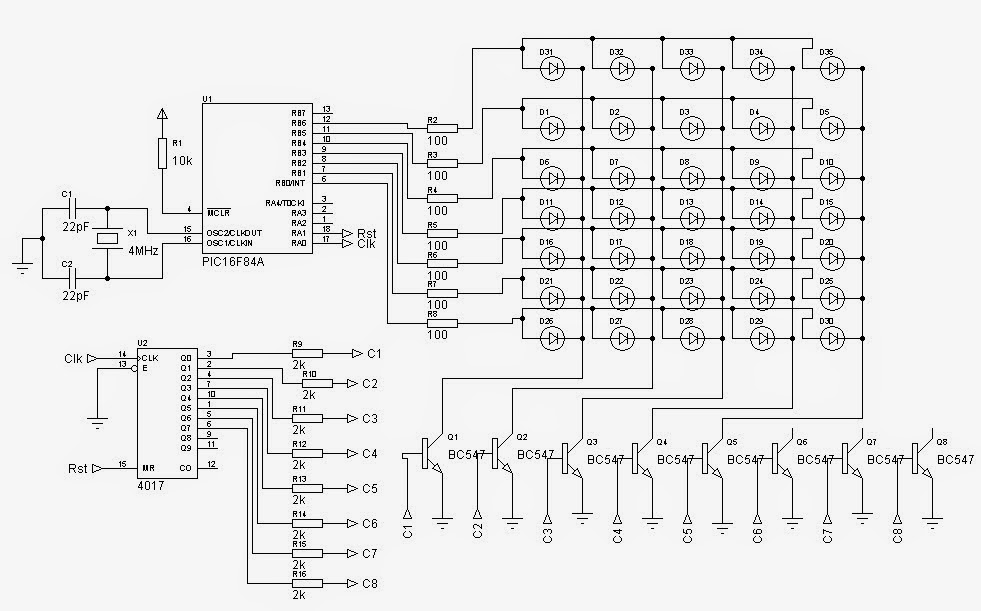


Figure 3: Schematic of the System
The PIC16F84A Microcontroller controls the LED matrix array and the 4017 decade counter. The decade counter 4017 scans the dot matrix columns via the transistors at rate greater than 75Hz so that persistence of vision required for the message display can be actualized. The power capability of the column transistors will determine the brightness of LEDs used for a given dot matrix display system!
In order to determine the appropriate hex values for display symbols in software, the symbols patterns are first designed as shown in figure 4 and figure 5. Figure 4 shows the design for alphabets A to Z, while figure 5 shows the design for numerals 0 to 9. The symbols can still be re-designed to suit the choice and taste of a programmer.
Figure 4: A to Z signs hex values
Figure 5: 0 to 9 signs hex values
The PIC assembly code for the dot matrix system is shown in the scroll box below. To understand the dot matrix code and make necessary modifications that suits individual application needs, the programmer must know how to write codes using PIC assembly language - PIC Assembly programming.
Start ORG 0x00 ;program starting point
BSF 03,5 ; go to bank 1 to set up ports
MOVLW 00h
MOVWF 05h
MOVWF 06h
BCF 03,5
afresh ; This routine make message scroll from right to left
movlw 00h
movwf 10h ;file 10h is the table pointer
getnext movlw 0b4h ;scroll speed value!!!!!!!!!!!!
movwf 11h ;file containing the scroll speed value
incf 10h,1 ;increment file to point to the next pattern on the table
movf 10h,0
continue movf 10h,0
call tablePattern
movwf 13h ;store pattern from table to temp file
xorlw 0aah ;checks to restart display
btfsc 03,2 ;check when to goto afresh
goto afresh
call Shift
movf 13h,0
movwf 1bh ;last ghost file for modification!!!
checkspeed decfsz 11h,1
goto kallscan
goto getnext
kallscan call scan
goto checkspeed
Shift ;Shift routine gives the "movement" effect on the screen
movlw 14h
movwf 04h
movlw .8
movwf 0dh
shiftstuff incf 04h,1
MOVF 00h,0 ;Move file 15h to W
decf 04h,1
MOVWF 00h ;Move W to file 31h and so on
incf 04h,1
decfsz 0dh,1
goto shiftstuff
RETURN
scan ;the subroutine scans the display pattern
BSF 05,1 ;Reset 4017
NOP
BCF 05,1
movlw 14h
movwf 04h
movlw .8
movwf 0dh
loop2 movf 00h,0
movwf 06h
CALL DelD
incf 04h,1
decfsz 0dh,1
goto loop2
return
DelD ; subroutine for scan delay and clocking the 4017
movlw 60h
movwf 0fh
del DECFSZ 0fh,1 ;Delay for viewing the scan
GOTO del
MOVLW 00h
MOVWF 06
BSF 05,0 ;Clock the 4017 to
NOP ; the next output
BCF 05,0
RETURN
tablePattern ;Symbol patterns for information display
ADDWF 02h,1 ;Add W to Program Counter
RETLW 00h
retlw 00h
retlw 00h
retlw 3fh ;A 6
retlw 48h
retlw 48h
retlw 3fh
retlw 00h
retlw 00h
retlw 7fh ;B 6
retlw 49h
retlw 49h
retlw 36h
retlw 00h
retlw 00h
retlw 3eh ;C 5
retlw 41h
retlw 41h
retlw 22h
retlw 00h
retlw 00h
retlw 10h ;1, 5
retlw 20h
retlw 7fh
retlw 00h
retlw 00h
retlw 27h ;2, 6
retlw 49h
retlw 49h
retlw 49h
retlw 31h
retlw 00h
retlw 00h
retlw 22h ;3, 6
retlw 41h
retlw 49h
retlw 49h
retlw 36h
retlw 00h
retlw 00h
retlw 00h
retlw 00h
retlw 00h
retlw 00h
retlw 00h
retlw 00h
retlw 00h
retlw 00h
retlw 00h
retlw 00h
retlw 0aah
end
Results
See video of results below:
Dot matrix information display system
Really appreciating the topic explored and added valuable comments. An information display software is an essential factor for the success of the digital display board.
ReplyDeleteGood morning sir please assembly code for 8051 microcontroller
ReplyDeleteHI
ReplyDeleteHOW CAN I MAKE DISPLAY EFFECT IN SCROLLING TEXT UP DOWN FADING FLASHING
If u want it then email me uchelectrotech@gmail.com then we discuss further
ReplyDelete