
Man and movement
The first Traffic lights were installed outside the Palace of Westminster London on 10th December 1868 to control the increasing number of vehicles there. However, according to some sources, the Traffic lights controller later exploded and injured the policeman operating it [1]. This Traffic Light design was adapted for controlling movement of vehicles and pedestrians at a critical busy junction.According to the UK Department of Transport, the number of vehicles plying the road has increased exponentially from about 4 million in 1950 to over 35 million in 2013. As a result, controlling movement of these vehicles has become very essential for the sake of a safe environment for all. Many junctions with traffic lights also have pedestrian crossings built into them. The pedestrian crossing use different indicators to prompt pedestrians when it is safe to cross upon pressing a push-button.
How the system works
The traffic light controller operates in a cyclic manner illuminating the red, amber and green lights indicators accordingly using the UK Traffic lights sequence. Whenever the system detects that the pedestrian push button is pressed, the control system should allow an ongoing vehicle traffic lights cycle to complete before attending to the pedestrian request to cross safely. Once the cycle finishes, the control system should alert the pedestrian that it is safe to cross by sounding an alarm with red illuminated. Upon pressing the push button, an LED will be illuminated to alert the pedestrian to wait for an alarm before crossing safely.Implementing the system
The complete schematic of the traffic light system is shown in figure 1.0 below. The traffic controller used for this implementation is PIC16F648A micro-controller. The device is a Flash-Based, 8-Bit CMOS device nanoWatt Technology.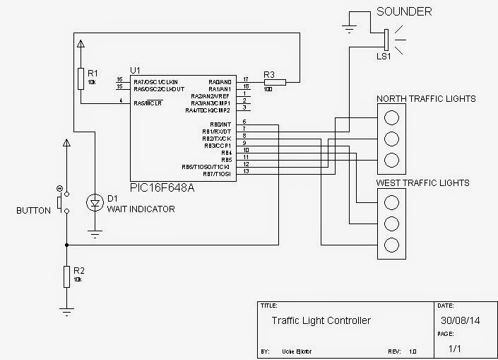
figure 1.0: System schematic
MPLAB IDE was the program software used to implement the C code using the inbuilt functions of the HI-TECH C compiler inside the MPLAB. The pedestrian push button request is implemented as an interrupt function. The complete code developed for the system is listed below:
/******************************************************************************************** C Program for Traffic Light Control
Author: Uche Ejiofor,24/08/14
Version: 1.1
**********************************************************************************************/
#include <htc.h> //include HITECH C Compiler header file
/*CONFIGURATION*/
__CONFIG(FOSC_INTOSCIO & WDTE_OFF & PWRTE_ON & BOREN_OFF & LVP_OFF & CP_OFF & CPD_OFF);
#define _XTAL_FREQ 4000000L //INTERNAL 4MHz CLOCK
// GLOBAL VARIABLE DECLARATION
unsigned char IntFile;
/*CODE ORIGIN*/
void main()
{
//OSCF=0X01; //INTOSC Oscillator Frequency set at 48KHZ
GIE = 1; // enable general interrupt
INTE = 1; //INTERRUPTS at pin RB0/INT enabled
INTEDG = 1; //RISING-EDGE TRIGGERD INTERRUPT ENABLED AT PIN RBO/INT
TRISA=0x00; //ALL pins at PORTA SET to OUTPUT PORT
TRISB=0x01; //PORTB RB0 pin SET to input, rest OUTPUT
PORTB=0x00; //clear PORTB for wrong signalling
while(1){
PORTB=0x90; //NORTH RED, WEST AMBER
__delay_ms(4000); //LOOP 4 TIMES, 4-SECOND DELAY
PORTB=0xD0; //NORTH RED AND AMBER, WEST RED
__delay_ms(4000); //LOOP 4 TIMES, 4-SECOND DELAY
PORTB=0x30; //NORTH GREEN, WEST RED
__delay_ms(10000); //LOOP 10 TIMES, 25-SECOND DELAY
PORTB=0x50; //NORTH AMBER, WEST RED
__delay_ms(4000); //LOOP 4 TIMES, 4-SECOND DELAY
PORTB=0x90; //NORTH RED, SDRY RED
__delay_ms(4000); //LOOP 4 TIMES, 4-SECOND DELAY
PORTB=0x98; //NORTH RED, WEST RED AND AMBER
__delay_ms(4000); //LOOP 4 TIMES, 4-SECOND DELAY
PORTB=0x84; //NORTH RED, WEST GREEN
__delay_ms(10000); //LOOP 25 TIMES, 25-SECOND DELAY
PORTB=0x88; //NORTH RED, WEST AMBER
__delay_ms(4000); //LOOP 4 TIMES, 4-SECOND DELAY
if (IntFile==0xFF){ //Check if there was a pin change on RB0/INT pin
RA0 = 0;
PORTB=0x92; //NORTH TRAFFIC RED, WEST TRAFFIC RED, PIEZZO SOUNDER ACTIVATED
__delay_ms(10000); //LOOP 15 TIMES, 15-SECOND DELAY
IntFile = 0; //clear interrupt bit
}
} //END WHILE
} //END MAIN
void interrupt isr(void) // Interrupt function
{
if(INTF==1){ // check if pedestrian button is pressed
RA0 = 1; //light up LED for wait
IntFile = 0xFF;
INTF=0; // clear flag bit
}
return;
}
Results
Video of results located in media 1 can be played to appreciate the system demonstration.
Media 1: Traffic light video of results
Hi there! Nice stuff, do keep me posted when you post again something like this!
ReplyDeleteFlush Mount Lights
hello, do you have the complete design process video
ReplyDelete